Michael Carusi reached out to initiate a super cool project, one of my favourites to date; A KTM 520 flat track bike. The connection came from a good friend Nigel Petrie (Engineered to Slide), who built a titanium exhaust for Michael’s last project; a KTM 500cc flat track bike (shown below).
Michael Carusi’s ‘Project Flat Track’ , Image: Andrew Jones from Machines That Dream
Naturally I followed along with this whole build, Michael collaborated with quite a few companies/people to make this bike truly one of a kind (@projectflattrack).
I got in contact with Michael when he put up a post looking for someone to do some modelling/rendering. I really threw myself into the deep end taking on this project – but I learnt a lot from it. I’d never done a rendering project requiring such high detail.
Michael sent through some ideas and inspiration pictures and I went to work.
If you aren’t familiar with how meshing works, it’s an amalgamation of points in space that are all connected by lines. These lines are filled in to create faces. Many connected faces make up the surface you see in the renders. The mesh construction of the fuel tank is shown below.
This project took a lot of time and a lot of that was spent learning new modelling and rendering techniques.
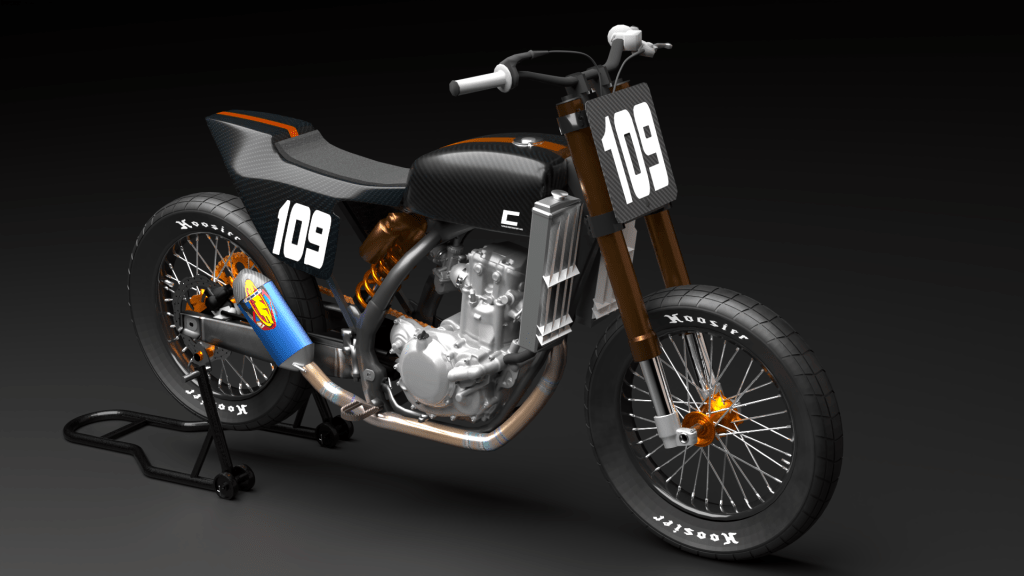
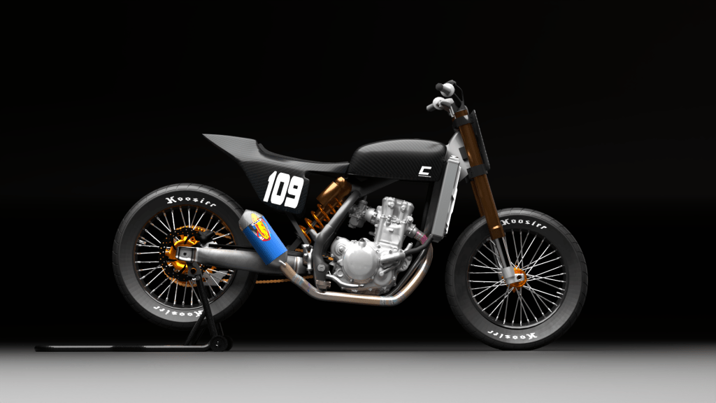
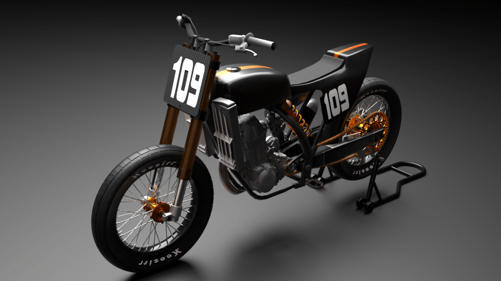
The most enjoyable parts to create were the FMF exhaust and the Hoosier flat track tyres.
After every iteration of changes you can see the model develop, and after every step you’ll always find something else to improve on.
Some of the final renders are shown below:
Thanks Michael for the opportunity to work on this project, I can’t wait to see how this build turns out!
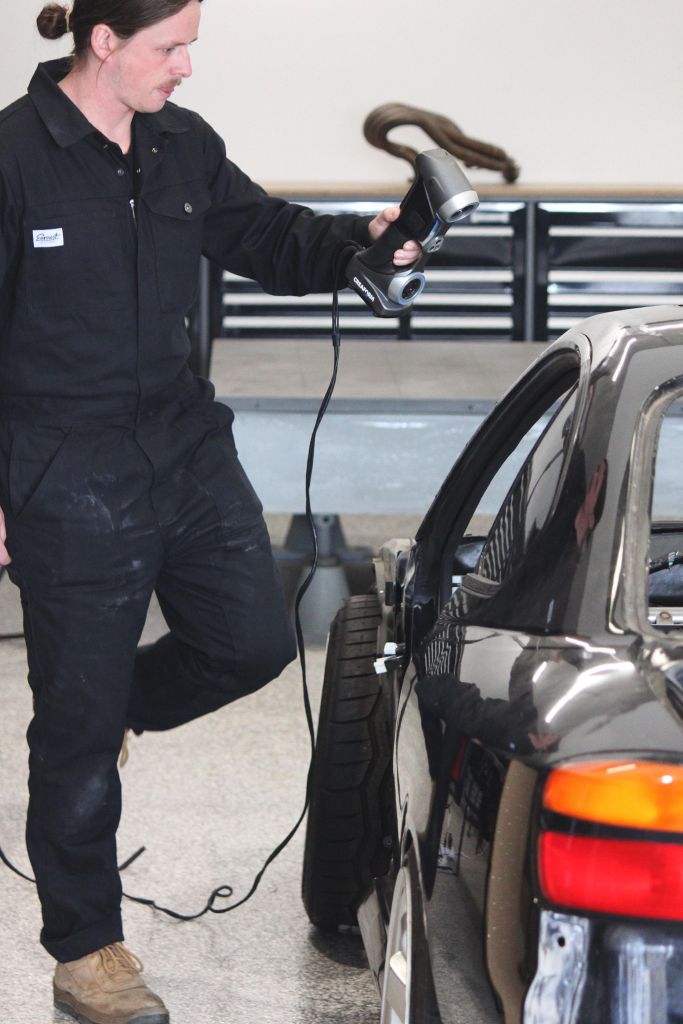
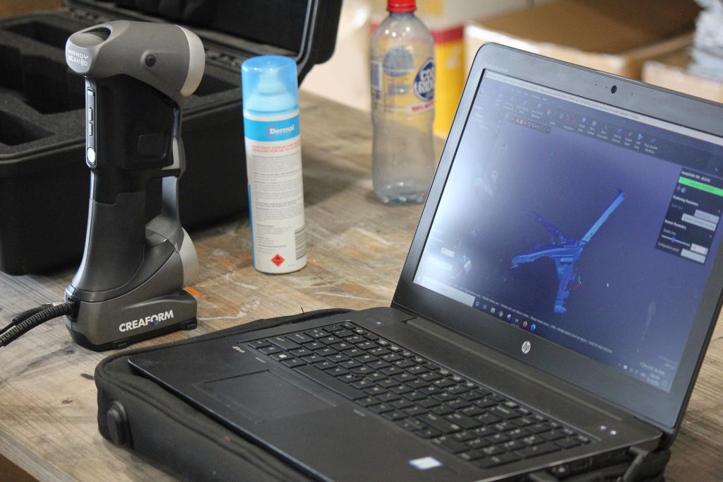
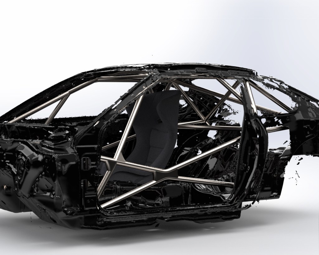
Nigel at Engineered To Slide has a Nissan S15 that he’s turning into a race/track car. While working on the car he’s been filming every step and producing online courses for ETSFab. Nigel’s built plenty of roll cages before, but this time he wanted to show some of the process involved in doing it professionally and getting it FIA approved. Luckily, Deakin University has a Creaform 3D scanner they were happy to lend us. I 3D scanned the car’s interior and designed a roll cage which we could then do FEA (Finite Element Analysis) on.
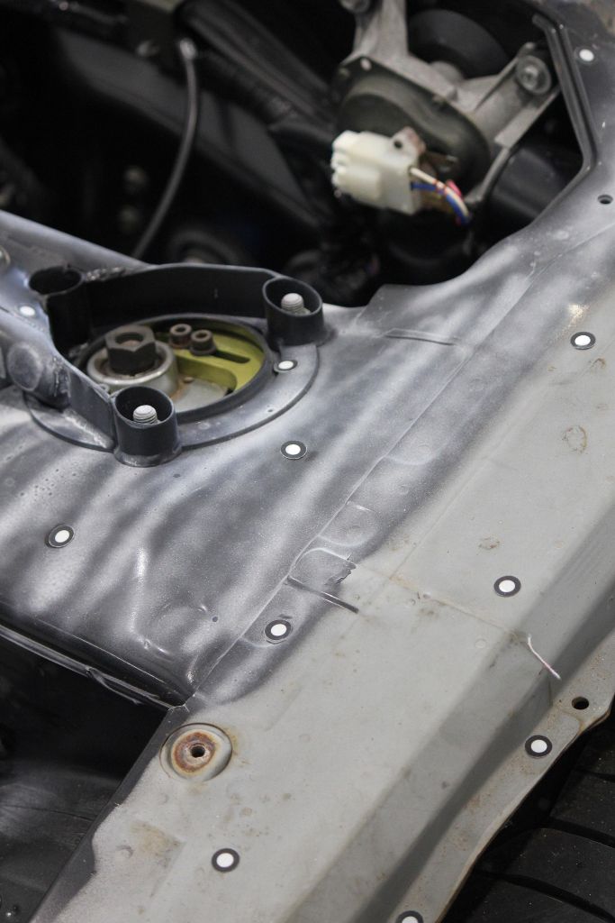
Everything in the car had to be stripped out, only the bare metal shell left. I began researching 3D scanners and practiced on a few small parts of the car, I found that black reflective surfaces are very hard to scan… The S15 is gloss black – unlucky!
We required a white, dust-like spray to cover the painted black surface to prevent the light being absorbed into the black paint, this meant the light was reflected for the scanner to read.
The scanner uses small sticker dots to keep track of where it is at any point. I spent a lot of time crawling around in the car putting in these dots, all spaced randomly about 6 inches apart. Then I used the spray to dust the most glossy black surfaces, under the seats and carpet was mostly primer which scans really well.
I began scanning from the middle of the car floor (trans tunnel) to the outside, then up the pillars and across the roof. This will ensure the scan is accurate and doesn’t begin to warp/walk around. I must say it will be a lot easier next time I scan a car, I learnt a lot about how the scanner works and the techniques used to make the process efficient.
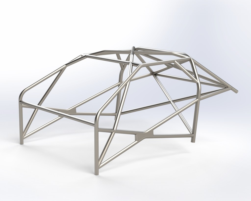
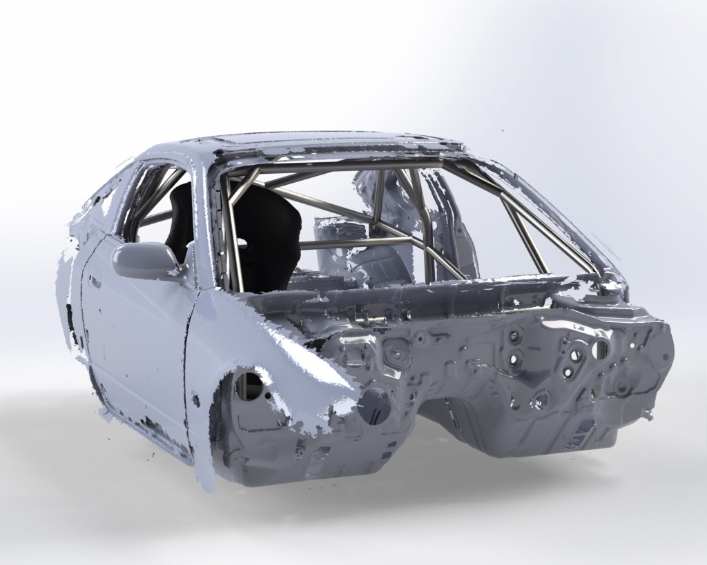
From here I exported the file to a CAD (Computer Aided Design) program and began laying out the roll cage inside the 3D scanned body.
Initially we wanted to use a special type of automotive high carbon steel for the cage but later found out that it is treated the same as Chromoly in the racing regulations. This means our cage would have had to adhere to the minimum tube sizes of Chromoly even though the new material would be 2-3 times stronger.
To use Chromoly or our other steel choice the cage would’ve had to go through FEA testing and be FIA approved, this costs around $4,000. In the end we opted for Mild Steel as the material choice as we could then get the cage MA (CAMS) affiliated which is cheaper (~$200). The weight difference between the initial design and the Mild Steel design is around 15kg due to the thinner tube walls, There was about the same weight of sound deadening in the car which we chipped out and removed for free. The $4000 for a 15kg gain just wasn’t worth it. Hopefully the rules can be adjusted to freely allow for materials other than Chromoly and Mild Steel in the future.
After the design was finished I completed some FEA testing using New Zealand’s governing body for motorsport regulations, this is because Motorsport Australia do not specify any force loads, they only allow to you design it a specific way that they’ve deemed safe (called schedule J). The FIA also doesn’t specify any loads, instead you must send your design to be approved by their affiliated companies, that’s the $4000 I mentioned before. The cage passed the FEA tests I did and we considered the design work finished. Nigel then commenced the process of fabricating the cage and filming it for his course. We had some hoops to jump through with cost and regulations but in the end I’m pleased with the roll cage design and can’t wait to see the car out on track!
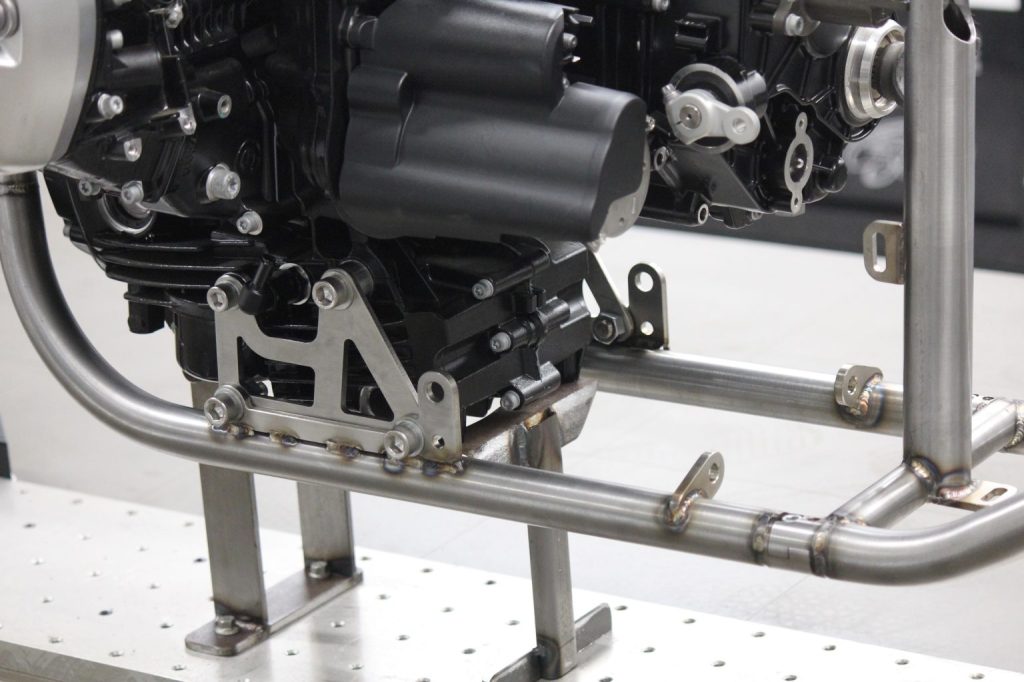
Images of car and roll cage fabrication supplied by Nigel Petrie (Engineered To Slide)
Precursor:The work I do at Engineered To Slide is only a small portion of what is required for these projects, the results remain solely the product of Nigel’s hard work and years of experience, I’m just called in to help on the CAD side of things. None of this would be possible without the opportunities and teachings Nigel has offered in the last few years.
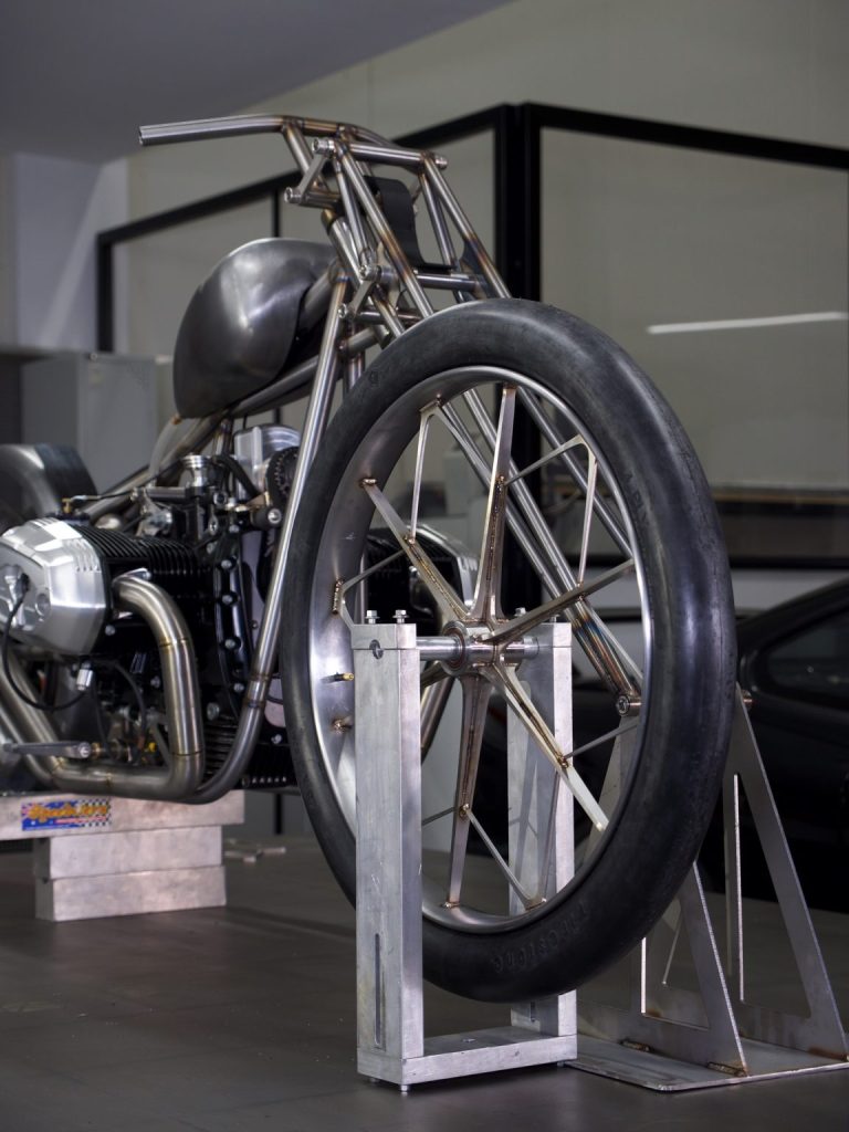
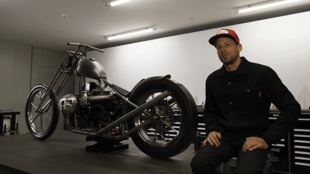
Back in early 2019 Nigel was asked by BMW Motorrad to build a chopper around their RnineT engine platform which is a 1170cc horizontally opposed twin cylinder (boxer). I was in the second year of my Mechanical Engineering (Honours) degree at Deakin University when I had scored myself some work with Nigel, who had just moved his business onto the campus into a workshop at Manufutures. I used to go in to ETS roughly once a week and spend some time drawing up parts in CAD for the BMW chopper and an electric bike project. It started off with small laser cut parts such as engine mounts.
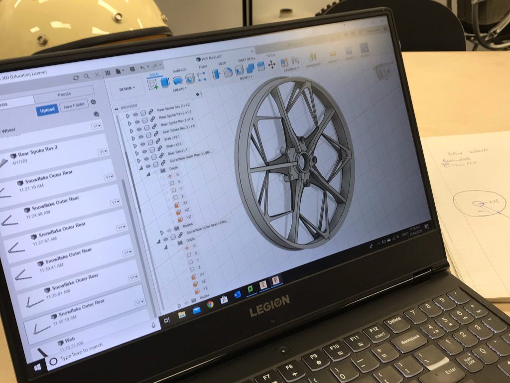
As the project moved along Nigel started dreaming up all sorts of crazy ideas about wheel designs. When he told me he wanted to make his own set of wheels I thought he was mad, then he told me he wanted me to model them up in CAD. Eventually he tracked down an old cast snowflake rim that was similar to what he had in mind. I went to work on designing up a snowflake wheel set to be CNC machined.
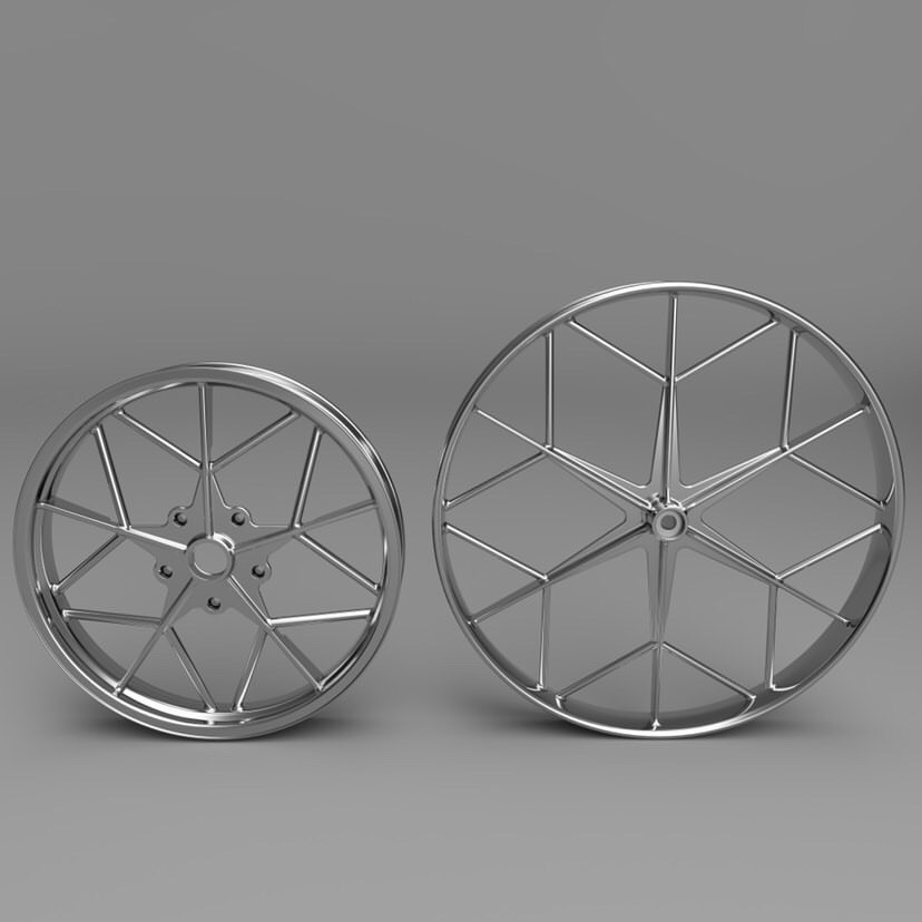
During the process of designing this up, Nigel also had a friend do some renders of his own take on the wheel set (@cornerstone.mfg) which are shown below. These looked great and helped guide our decision making in design, we just had to figure out best how to build them.
After the CNC wheel designs were done we spoke to some people about getting them machined, it was going to cost $12,000 which was just too high to justify.
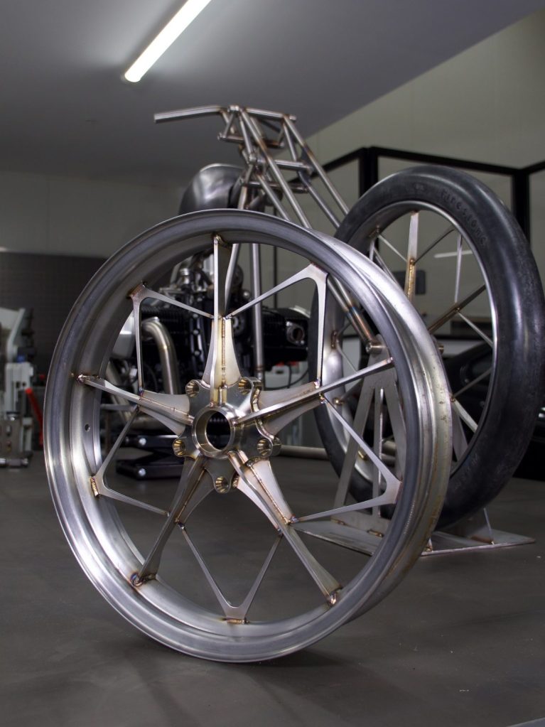
After sitting on that idea for some time Nigel had an idea; laser cut each piece and TIG weld them together. This meant we had some big changes to make to the CAD model to accommodate the new fabrication method. I began piecing together an assembly of 2D parts to form the spokes and snowflake pattern. Nigel bought two outer rim blanks and I modelled a couple of hubs to be CNC machined.
Eventually we came to a final design and the parts were sent off for laser cutting/machining:
Watching these wheels come to life through the power of Nigel and his welder was great. From what I can remember, this was the first cool thing I’d designed at ETS that wasn’t just a small tab or engine mount. I was stoked, and still am. I’m very greatful for the opportunities Nigel provided throughout my studies. This project was a real testament to his fabrication skills and creativity.